
Guides
Create an L-bracket with a screw hole
Model a 60 x 40 x 40 mm L-bracket with 4 mm walls and a 5 mm screw hole from two boxes and a cylinder, then save and export it.
Screenshots show the English interface.
Start a new design
On the dashboard, choose Create new 3D design. Sizes are entered in millimetres; if the fields show another unit, open Workspace settings and set Units to Metric (Default). Millimetres set the size of the model; how closely the print matches depends on your printer, material and slicer settings.
Make the base plate
Open Add shape and choose Box. Under Properties, type Length 40, Width 60 and Height 4, pressing Enter after each value. The number fields are more precise than the sliders.
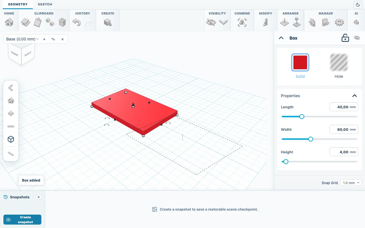
Fig. 01Base plate: Length 40, Width 60, Height 4. Add the upright wall
Add a second Box and type Length 4, Width 60 and Height 40. It appears in the middle of the plate; the next step moves it to the edge.
Move the wall to the edge
Press Ctrl+A (Cmd+A on a Mac) to select both boxes, then open Modify and choose Align. Dots appear around the selection; hover over one to see its name. Click the back dot to move the wall flush with the back edge of the plate. Both boxes stand on the workplane, so bottom is already aligned.
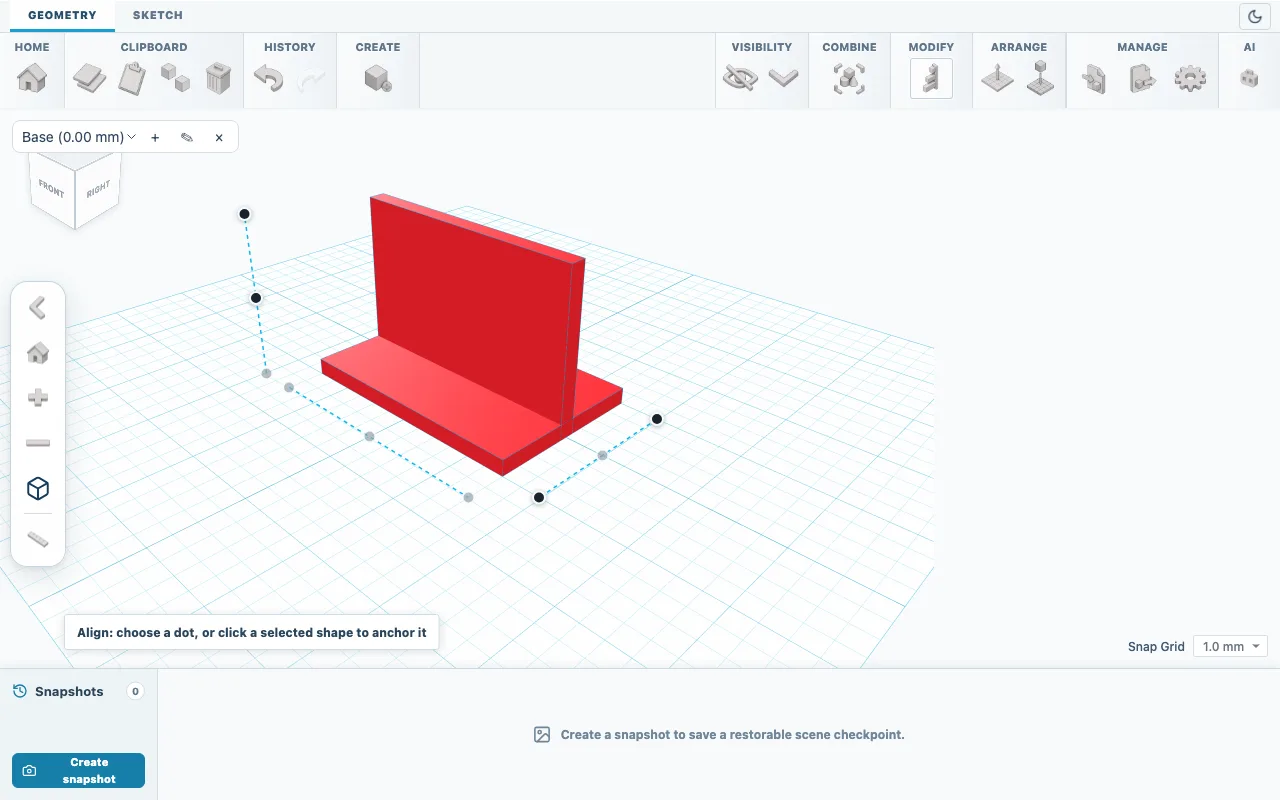
Fig. 02Align shows dots along the edges of the selection. Join the boxes
Click Align again to finish aligning. With both boxes still selected, open Combine and choose Boolean Union. The result is one solid, and Properties shows Length 40, Width 60 and Height 40.
Add the screw hole
Add a Cylinder and click Hole in its settings. Type Length 5, Width 5 and Height 10. The hole is taller than the 4 mm plate, so it cuts all the way through.
Center the hole
Press Ctrl+A and choose Align. Click the bracket to make it the anchor, so it stays in place, then click the center and middle dots that lie on the workplane. Dots that are already aligned are disabled. The hole is now 30 mm from each side and 20 mm from the front edge.
Cut the hole
Click Align again to finish. With the bracket and the hole selected, open Combine and choose Boolean Cut. The bracket keeps its 60 x 40 x 40 mm size and now has a 5 mm hole through the base.
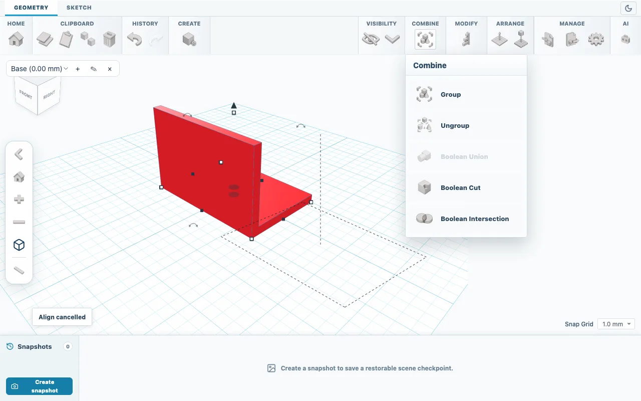
Fig. 03Boolean Cut becomes available once a solid and a hole are selected. Save and export
Open Export, choose SKF and click Save SketchForge Project to keep an editable copy. Then choose 3MF or STL and export the file for your slicer.
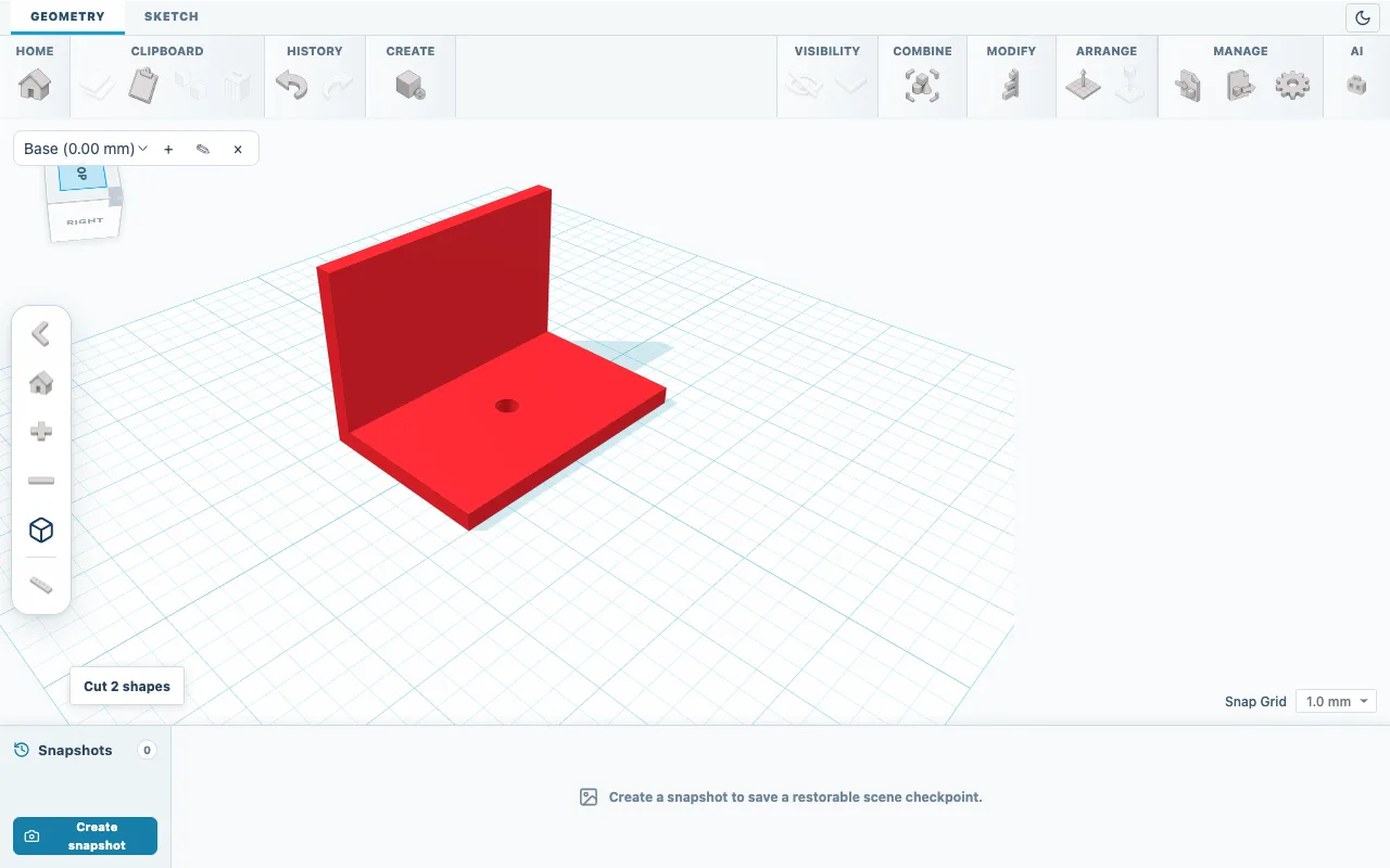
Fig. 04Finished bracket: 60 x 40 x 40 mm with a 5 mm hole.
Check the result
Check the overall size in Properties: Length 40, Width 60, Height 40. In Top view on the view cube, you should see straight through the hole.
If something goes wrong
- Boolean Cut is greyed out
- Select at least one solid and at least one shape set to Hole. Locked shapes do not count.
- The exported file has no hole
- Shapes set to Hole are left out of STL, 3MF and OBJ files. Apply Boolean Cut before you export.
- A step went wrong
- Use Undo or Ctrl+Z. Create snapshot saves a checkpoint you can return to later.